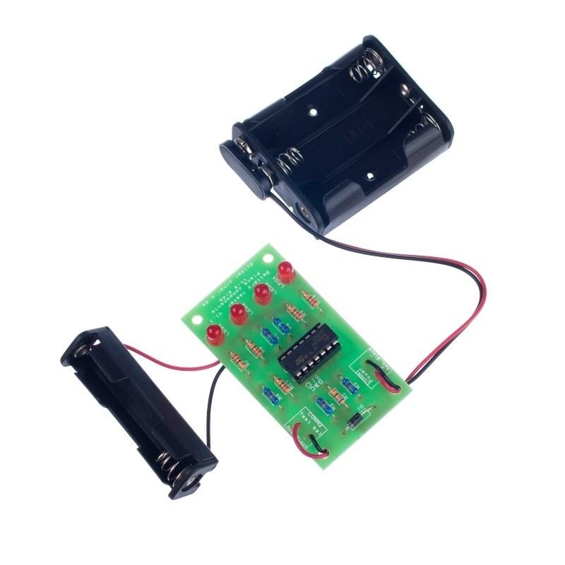
This kit uses a single AA battery holder into which the user places a battery. LEDs then illuminate to show the remaining capacity of the battery. The circuit uses a quad operational amplifier to provide a reference voltage and comparators to determine which LEDs should go on. This makes it a great kit for studying operational amplifiers.
Testing of the kit can be performed using an adjustable power supply, or with a circuit tester (consisting of an AA battery holder, variable resistor & crocodile clips).
Note: this kit requires soldering.
Features:
- Displays battery charge level with 4 LEDs.
- Great for showing how operational amplifiers work.
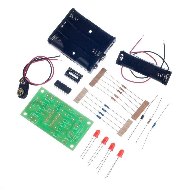
Contents:
- 1 x PP3 Battery Clip Lead (Heavy Duty).
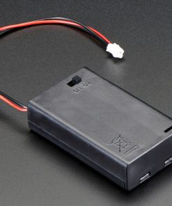
- 1 x 3xAA Battery Cage with Clip.
- 1 x LM324 Quad Op Amp.
- 1 x IC Socket 14 Pin.
- 1 x 1N4001 Diode.
- 4 x Red 5mm Diffused LED – 275mCd.
- 1 x 680Ω Resistor.
- 5 x 220Ω Resistor.
- 4 x 22KΩ Resistor.
- 1 x 100KΩ Resistor.
- 1 x 1xAA Battery Cage with Leads.
- 1 x Battery Tester PCB.
Dimensions:
- PCB Length: 68.5mm.
- PCB Width: 38mm.
Requires:
- 4 x AA Batteries.
Resources:
-
Click here to download the essential information.

-
Click here to download the full teaching resources.

This kit is supplied in a simple grip seal bag.
| Description | Unassembled kit |
|---|
Fast Shipping and Professional Packaging
Because of our long-standing partnership with UPS, FedEx, DHL and many other leading global carriers, we can provide various shipping options. Our warehouse staff is highly trained and will pack the items according to our exact and precise specifications. Before shipping, your goods will be thoroughly examined and secured. We deliver to thousands of customers every day from all over the world. This is a sign of our dedication to being the largest online retailer worldwide. There are distribution centers as well as warehouses located in Europe as well as the USA.
Note: Orders with more than one product are assigned a specific processing period dependent on the particular item.
Before shipping, we will examine the items ordered carefully before shipping. The majority of orders are shipped within 48 hours. The time to deliver varies from 3-7 days.
Returns
The stock is constantly changing and cannot be fully controlled by us due to the involvement of many parties including the factory and our warehouse. This means that the actual stock could alter at any time. Be aware that it is possible that your order could be out of stock after you have made the order.
Our policy lasts thirty days. If you haven't received your item within 30 days, we're unable to offer the option of a refund or exchange.
You are able to return an item when it's unopened and is in the same condition as when you first received it. It should also be returned in its original packaging.
Related products
Uncategorized
Uncategorized
Uncategorized
Uncategorized
part, parts, battery, 9v, clip, power
