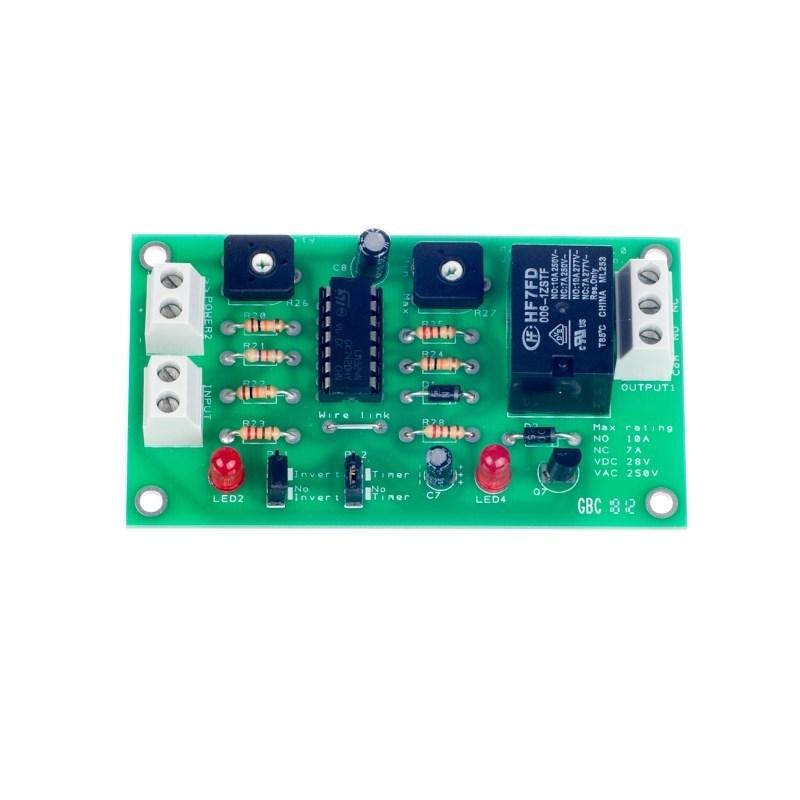
This is a versatile relay board kit that can easily be configured via jumpers and trimmer potentiometers to do a range of tasks.
Most sensor and switches can be connected to the input of the board and the trigger level set for the input device. This can be inverted if required, then there is the option to feed this straight to the relay or a timer of up to 25 minutes can be used. Irrespective of the state of the ‘invert’ jumper whenever the sense LED goes from off to on the timer restarts.#
The board can run off any voltage from 4.5 to 6 volts.
The output cans switch DC or mains.
This datasheet details what the board does and how to use it along with some worked examples. A more detailed set of information including the build instructions & how to configure the kit can also be downloaded.
Click here to download the full teaching notes ![]()
WARNING: Using mains electricity can be dangerous and should only be attempted by qualified people.
Note: this kit requires soldering
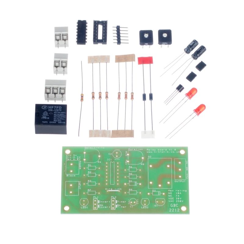
This kit includes:
- 3 x 100Kohm resistors
- 3 x 220ohm resistors
- 1 x 47Kohm resistors
- 1 x 1Mohm potentiometer
- 1 x 10Mohm potentiometer
- 2 x 1N4001 diodes
- 2 x 5mm red LEDs
- 1 x 100uF capacitors, electrolytic
- 1 x 4.7uF capacitors, electrolytic
- 1 x 2N7000 n-channel FET
- 2 x 2 way terminal blocks
- 1 x 3 way terminal blocks
- 1 x LM324 operational amplifier IC
- 1 x 14 pin IC holder
- 2 x 3 way pinstrip
- 2 x Jumpers
- 1 x Relay
- 1 x Relay board PCB
PCB dimensions: 86.5mm x 49mm.
| Description | Relay board disassembled |
|---|
Fast Shipping and Professional Packaging
Because of our long-standing partnership with UPS, FedEx, DHL and many other leading global carriers, we can provide various shipping options. Our warehouse staff is highly trained and will pack the items according to our exact and precise specifications. Before shipping, your goods will be thoroughly examined and secured. We deliver to thousands of customers every day from all over the world. This is a sign of our dedication to being the largest online retailer worldwide. There are distribution centers as well as warehouses located in Europe as well as the USA.
Note: Orders with more than one product are assigned a specific processing period dependent on the particular item.
Before shipping, we will examine the items ordered carefully before shipping. The majority of orders are shipped within 48 hours. The time to deliver varies from 3-7 days.
Returns
The stock is constantly changing and cannot be fully controlled by us due to the involvement of many parties including the factory and our warehouse. This means that the actual stock could alter at any time. Be aware that it is possible that your order could be out of stock after you have made the order.
Our policy lasts thirty days. If you haven't received your item within 30 days, we're unable to offer the option of a refund or exchange.
You are able to return an item when it's unopened and is in the same condition as when you first received it. It should also be returned in its original packaging.
Related products
part, parts, battery, 9v, clip, power
Uncategorized
Uncategorized
